I have got UART on IoT card. Data transmission (Rx/Tx) works perfectly. However I have got problem with controlling RTS/CTS lines.
MangOH green:
Line RTS looks fine. When I change RTS on MangOH, CTS changes on connected device. BUT.
When I change RTS on a device, CTS on MangOH does not react (It is always set).
FX30S:
Unable to control RTS/CTS.
Why FX30 and MangOH behave differently? Why CTS flag is always set?
I have disabled CRTSCTS intentionally (please look at my code attr.c_cflag &= ~CRTSCTS;). I don’t want hardware control, I want software control. FX30 and mangOH green are unable to read CTS status. I can set up RTS line on mangOH green but I cannot do it on FX30. Please look at source code in my post.
I would be extremely surprised, if FX30 does not have 4 wires UART. Please look at documentation of FX30, page 53 figure 3-6. FX30S has got RS485. FX30S does not use RTS/CTS for flow control? I do not think so.
I have noticed one more thing. I can control RTS line on mangOH green as I said before. However I can control RTS line on UART1 but I can NOT control RTS line on UART2.
UART2 on mangOH green behaves like both UARTs on FX30S.
it all depends on the module you are using.
WPx5 : UART1 is 4 wire and UART2 is 2 wire.
so on a mangOH Green/Red: IoT card slot will show 4 wire (UART1)
on FX30, UART2 is used on IoT card , so it is 2 wire.
i am not sure why UART1 is showing as 2 wire for you on FX30.
Anyways, what is the problem you are trying to solve?
I want to use RTS/CTS lines to control flow on my designed IoT card. Unfortunately I cannot do it. All technical drawings show RTS/CTS lines, so I have assumed, both UARTS are 4-wire. My assumption was wrong. After your last response, I checked architecture of WP8548, WP7502, WP7504. All 3 processors has got 2 UARTS. UART1 is 8-wire and UART2 is only 2-wire.
I cannot use RTS/CTS lines because:
FX30 has got UART2 on IoT card, so only Rx,Tx are available (no RTS/CTS). FX30S has got RS232 on the back based on UART1, but lines RTS/CTS are dead/unresponsive.
I have got UART1 on mangOH green on IoT0 or IoT1 slot. But I can control only RTS line. I cannot read status of CTS.
mangOH Red has got UART1 on IoT slot, but I don’t know if I can control RTS/CTS lines, because I don’t have the board.
I can NOT use RTS/CTS lines on my IoT card because it will not be working. FX30 has not got MUX to redirect UART1 to IoT. So it will not be working because of design of FX30. mangOH green thinks that CTS line is always set, so my IoT will not be working.
I like legato and mangOH project a lot, but this is a little disappointing.
Lets close the post. I will try to solve it other way.
I dont believe there is any technical reason related to mangOH that is causing issues with item 2.
And yes, for item 3, it is a 4 wire UARt on IoT slot.
You said :
“I dont believe there is any technical reason related to mangOH that is causing issues with item 2.”
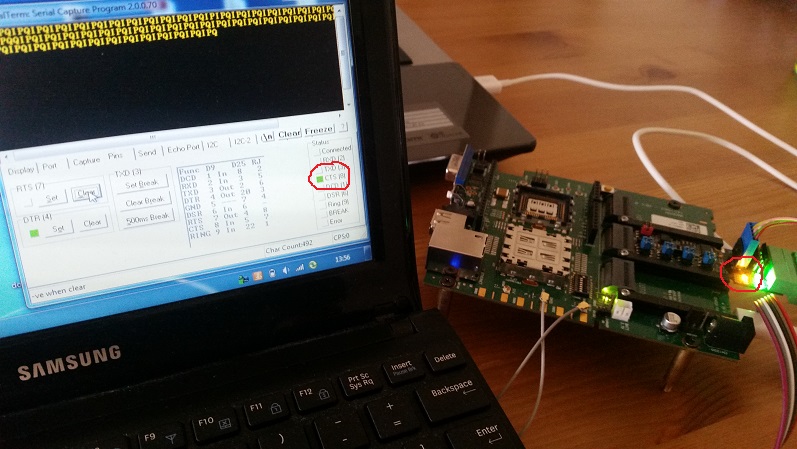
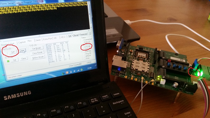
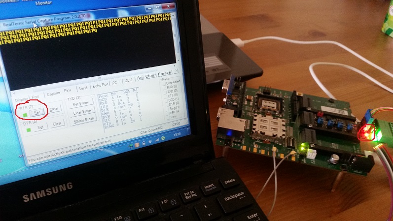
I put in Universal Converter to mangOH green and I have connected the unit with PC. When program on mangOH sets RTS line, CTS is ON on RealTerm program and orange RTS diode is ON on Universal Converter
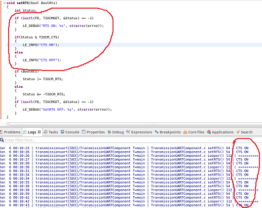
Everything is ok so far. But When I read CTS status on mangOH green programmatically, status of CTS is always on (“CTS ON” on terminal). Please look at the source:
int Status;

if (ioctl(FD, TIOCMGET, &Status) == -1)
{
	LE_DEBUG("RTS ON: %s", strerror(errno));
}

if(Status & TIOCM_CTS)
{
	LE_INFO("CTS ON");
}
else
{
	LE_INFO("CTS OFF");
}

if (BoolRts)
{
	Status |= TIOCM_RTS;
}
else
{
	Status &= ~TIOCM_RTS;
}
if (ioctl(FD, TIOCMSET, &Status) == -1)
{
	LE_DEBUG("SetRTS OFF: %s", strerror(errno));
}
You DO NOT have to believe, it is the issue with mangOH green, but I can proof it that IT IS.
If you assume mangOH green is always a host, so it is fine, because mangOH green will not have to read CTS line. But if someone uses mangOH as client, it will be a problem.
If I am doing something wrong and I CAN read CTS line in other way, please let me know.