I have connected an i2c sensor to raspberry pi i2c connectors (SDA, SCL). The address of the sensor is 0x5A. However, the sensor is not being detected.
Following is the output of ls -l /dev/i2c*
Where can I find which i2c port belong to SD3 SC3 ports?
Also when I tried to detect the sensor using i2cdetect -y -r
Your device should appear on Bus 8. Bus 4 is the bus coming out of the SoC and 5, 6, 7 and 8 are the sub-busses off the switch.
I was also unable to use the quick-write version of i2cdetect, but the read version worked fine. I did get the slave not responding errors which made the console output unusable, but if I did:
i2cdetect -y -r 8 > /tmp/detected
I got a useful piece of output and the device was where I expected it to be with no problems. You could also ssh in and run i2cdetect to not have the spurious errors.
So, because of the way I2C works, everything on bus 4 is going to also appear to be on any of the busses downstream of the switch. So, your output is identical to mine (except my own device appears, as expected, on bus 8, on my board). My strong suspicion is that your device is in some way not working and that the mangOH is fine. i2cdetect is showing you that there’s a Linux driver loaded for the I2C switch (at address 0x71 on bus 4 and all other buses) and i2cdetect is fundamentally working. There’s not a lot that could be wrong with those symptoms other than your device having some connectivity issue.
I suppose it’s possible that the two zero-ohm resistors (R365 and 366) are somehow missing on your board but they certainly weren’t on mine (I ordered mine from Digikey).
To check the board, check to make sure the two I2C pins on the Raspberry Pi connector are both pulled to 3.3 volts. If they are, then the problem is almost certainly after that point. If they aren’t then there’s likely a physical problem with your board.
As for your second screen grab (i2cdetect using “write” mode), that does not work on this master interface. Not sure why, but read mode works fine.
For comparison’s sake, here’s my software versions:
Device: WP7702
IMEI: 352653090112913
IMEISV: 2
FSN: VU810385470210
Firmware Version: SWI9X06Y_02.14.04.00 a03347 jenkins 2018/02/19 06:13:56
Bootloader Version: SWI9X06Y_02.14.04.00 a03347 jenkins 2018/02/19 06:13:56
MCU Version: 002.007
PRI Part Number (PN): 9907365
PRI Revision: 001.004
Carrier PRI Name: GENERIC
Carrier PRI Revision: 001.012_000
SKU: 1103530
Last Reset Cause: Power Down
Resets Count: Expected: 52 Unexpected: 39
Err, you’re not testing what you think you’re testing. You need to use the DC voltage setting on your meter, not the “Battery/Pile” setting, which will draw current to ground. It looks like your meter is set to draw 5mA which will drag the bus down since the pull-ups are about 250uA.
I would strongly recommend never using the Battery/Pile setting on that meter unless you know exactly why you’re doing it (see page 11 of the volt meter’s manual for details).
Also, when you say this: “The sensor I am trying to test does not support 3.3v”… The I2C bus voltage of the mangOH board is 3.3 volts so if the sensor doesn’t see that as a “high” (it should but you don’t say what the sensor is so I can’t check the data sheet) then it isn’t going to work.
Sorry about that, this is a new multi meter I started to use. Indeed the voltage is 3.3v on SCL and SDA pins. Safe there not issues with the board.
I have got another model of the same sensor which supports 3.3v and I tested with arduino. After hooking it to MangoH Red the output of i2cdetect is exactly same as before. By the way the sensor I am testing is MLX90614 which has two models one 3.3 v and the other 5v.
@fgodfrey if the i2cdetect -y 8 doesn’t show up the address does it mean the sensor hasn’t responded with the discovery of the address ?
Well, “quick write” mode doesn’t seem to work on the WP7702 so you need to do i2cdetect -r -y 8, but yes, if it doesn’t show up, it means the sensor didn’t respond. However, there ARE some devices that don’t respond correctly to detection but do work so you may want to try throwing some commands at it and see if it responds. The data sheet for your part indicates that there are some non I2C modes that can be programed as power-on defaults, but since you said it works fine with an Arduino, that’s almost certainly not your issue.
At this point, other than the possibility that it’s working fine and just not responding to detection (some devices fail to correctly acknowledge bytes sent to them), I am out of ideas. What you have should work.
No problem! Glad you got it working! For what it’s worth, there’s a Linux driver for your thing if you’re interested that looks like it’ll do all the calculating for you and drop the values in /sys. I’ve never used this particular device though.
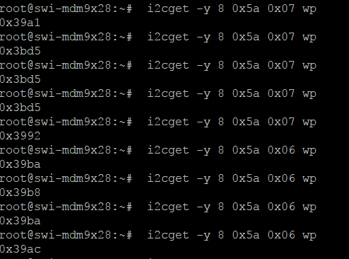
The reason some devices don’t respond to “detect” is because of the way it works. The protocol is that the master sends the device address to the slave. The slave is supposed to acknowledge by holding the bus low. However, some devices won’t acknowledge unless you send them a valid command and since i2cdetect doesn’t send a command, those devices won’t properly respond and thus won’t be detected. When you do i2cget you’re sending a valid command so the device acknowledges and you’re good to go.
I have written a simple tempReading app using the reference of the i2c/BatteryChargerReading tutorial under red. That is reading the values fine, however I haven’t used any drivers. This application uses i2c communication directly with the device without any drivers.
You mention a Linux driver which one is it where can I refer to ?